The architecture is based on a very simplified VHDL-like model [3]. In VHDL, a system is built up from Entities which perform the processing tasks. These Entities are connected by any number of Ports, which drive data from one Entity to the next. In a similar fashion, in the simulation software a basic processing unit is called a ProcessElement, and these can be connected together via DataPorts.
One of the major simplifications of the architecture compared to VHDL
is a very basic time-structure. Since the software is intended to
simulate the progress of real-time and readout data through a
correctly timed-in level-1 system, there is no attempt to simulate
anything below the sub-tick level. This means that the simulation
can progress tick-by-tick through each stage of the system, with the
downstream stages being processed first and the flow of control then
proceeds upstream. This simplification also leads to the restriction
that no feedback-like element can be simulated - the simulation can only
flow in one direction, and any attempt to use a `later' result upstream
will cause a simulation error.
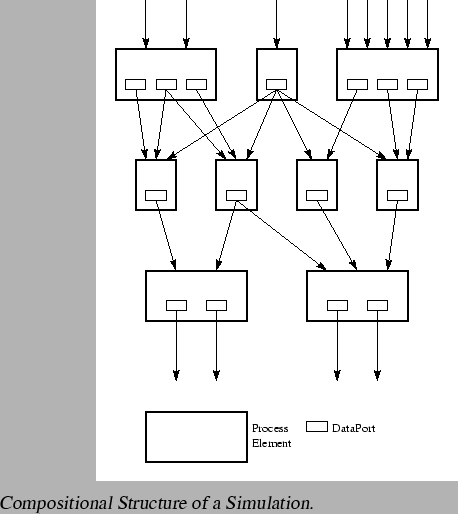
Another simplification is the treatment of DataPorts as all being
contained in a single ProcessElement. Any ProcessElement can contain
more than one DataPort. The contained DataPorts form the output
of the ProcessElement. Inputs to a ProcessElement are formed by
reference to the outputs of other ProcessElements. Any output can go
to more than one input. The situation is illustrated in
figure 3.
Other than providing the mechanism to process the flow of data, the
other main function of the framework is to provide a mechanism
for connecting inputs and outputs together. There are a few methods
provided to do this, and they all work on the principle that each
input and output is associated with a name and optionally a number.
Typical examples might be an algorithm with inputs names such as
`EMTower' 1, `HadTower' 2 and an output named `NumberOfHits'.
The final major structural feature of the modeling classes is the
ability to wrap a set of ProcessElements into a compound entity. This
provides a way to build up complex elements from simpler ones, and then use
them as if they were just another simple element providing outputs and
requiring inputs - all the internal complexity is hidden in the class
definition. This functionality is provided by the ProcessContainer
class.