The synchronisation issues discussed in the previous section require that some actions connected with trigger, TTC and BUSY signals must be executed either before or after actions in the trigger processor crates.
The specification for the BUSY module allows the output BUSY signal
to be set directly via a VME register.
Assuming our overall BUSY module is in the TTC crate, all the
above can be satisfied (I think!) using a two level run control
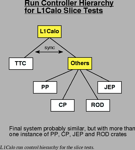
hierarchy where the TTC crate is separate from all the other crates.
It is then a simple matter in the overall L1Calo run controller to
select the order in which the actions in the ``TTC'' and ``Others''
controllers are executed in each transition.
Apart from possible concerns about actions in the ROD crate, all the
other crate actions can run in parallel.
Given these assumptions, a hierarchy of run controllers suitable for
the slice tests is shown in figure 3.5. In principle
the hierarchy for the final system is identical, except that there will
be more of each kind of crate. Also there will be controllers for the
receiver crates which will not be present at the slice test.